Mercedes-Benz E-Class: How to Replace Oxygen Sensor
Oxygen sensors, or "O2 sensors," are found in the exhaust system. They are subjected to high levels of heat from the engine. Over time, the sensors' ability to detect oxygen lessens, indicating it's time for a replacement. This how-to will guide you through the replacement, helping you make a successful repair.
This article applies to the Mercedes-Benz E-Class (2002-2009).
The Mercedes-Benz E-Class oxygen sensor is the main component for the emission control system. When it's not working properly, the engine computer cannot identify the correct air/fuel ratio. The catalytic converter can also become damaged. Unfortunately, a check engine light for an O2 sensor may not mean it needs to be replaced, and often a trip to the repair shop for troubleshooting is the best choice. If the O2 sensor(s) are determined to be the cause, then replacement is rather simple, requiring only an hour or two of your time.

Materials Needed
- O2 sensor socket (upstream O2 sensors)
- New O2 sensor(s)
- 22mm wrench
- 8mm nut driver
- Torque wrench
- Floor jack
- Two jack stands
- Two wheel chocks (optional)
- Block of wood
- Safety glasses
- Gloves
- Zip ties
- Flat head screwdriver
- Penetrating oil
- Anti-seize lubricant
- Diagonal cutters
- LiquidWrench
The E-Class has four O2 sensors that are named as follows:
- Bank 1 sensor 1 (upstream of catalytic converter)
- Bank 1 sensor 2 (downstream of catalytic converter)
- Bank 2 sensor 1 (upstream of catalytic converter)
- Bank 2 sensor 2 (downstream of catalytic converter)
This will be important when buying the new O2 sensor and if you decide to take the vehicle to a service center or parts store for diagnostics. Whether you decide to buy aftermarket or OEM (original equipment manufacturer), O2 sensors will negate the price. Generally, the higher-priced O2 sensors are considered more reliable.
Pro Tips
- Spray all of the fasteners that secure the O2 sensors with LiquidWrench the night before you attempt this project. They tend to get stuck because of the high-heat environment, and spraying them will make removal much easier.
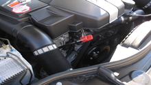
- Certain models and engines route the O2 sensor wiring above the engine near the firewall instead of the location in Figure 13.
Step 1 – Raise and support the vehicle
Apply the parking brake. Locate the jack points on each side of the vehicle.

With a jack, raise the vehicle on the right front jack pad, high enough to position a jack stand under the right rear jack pad. It is best to raise the vehicle in increments from spot to spot. This eliminates the chance of the vehicle moving on the jack stands. Move the jack to the rear differential (Figure 3) and raise the vehicle high enough with a block of wood to fit a jack stand under the left rear jack pad. Move the jack to the left front jack pad and raise the vehicle again to place a jack stand under the right front jack pad. Now use the oil pan (Figure 4) to raise the left front jack pad high enough for a jack stand to fit underneath it.
The jack pads may need to be installed on the vehicle, typically requiring one bolt to secure it to the body.
(Related Article: Mercedes-Benz E-Class: How to Jack Up Your Car - MBWorld.org)
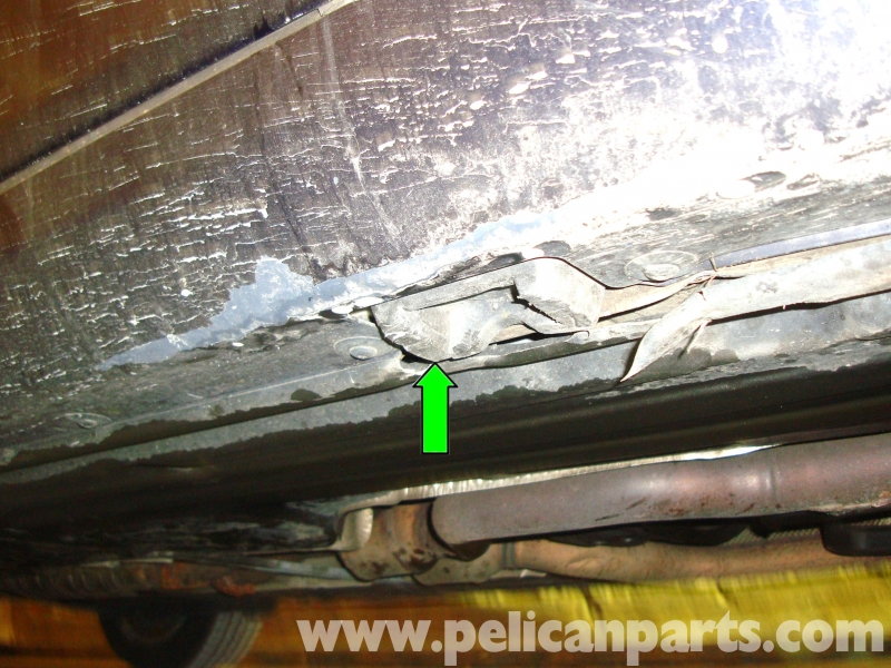
Figure 2. One of the four jack pads. 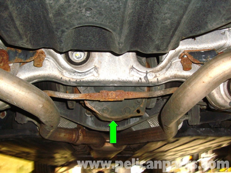
Figure 3. Position the jack to allow the block of wood to contact the bottom of the rear differential. 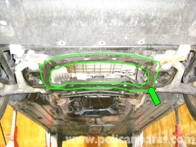
Figure 4. Position to jack to allow the block of wood to contact the oil pan.
Pro Tip
Depending on what you're comfortable working under, there may be enough room available with only the front of the vehicle raised. Use wheel chocks behind the rear wheels as a safety measure.
Step 2 – Remove the splash shields
Loosen the 8mm fasteners in the order shown in Figures 5-11. The fasteners are indicated by green arrows. Click each image to enlarge.
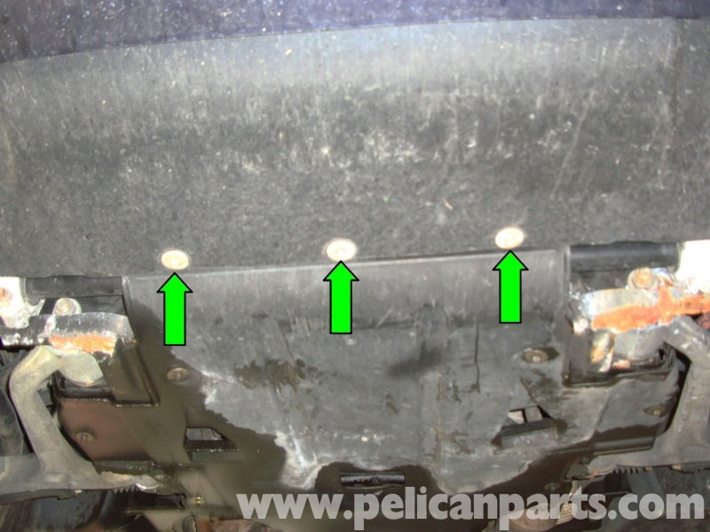
Figure 5. These fasteners are located on the bottom of the front bumper. 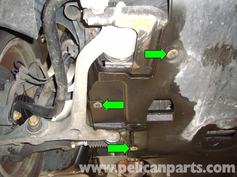
Figure 6. Remove the three fasteners located by the right lower control arm. 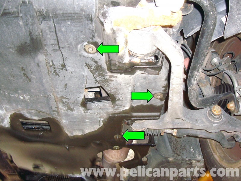
Figure 7. Remove the three fasteners located by the left lower control arm.
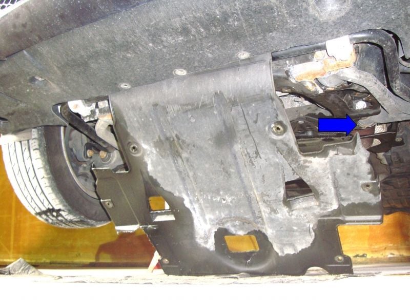
Figure 8. Lower the splash shield while pulling it towards the rear of the car. 
Figure 9. Remove the two fasteners located by the left exhaust pipe. 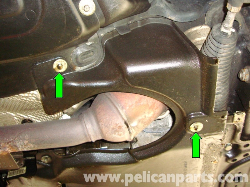
Figure 10. Remove the two fasteners located by the right exhaust pipe. 
Figure 11. Remove the two fasteners located below the transmission fluid pan.
Pro Tip
Now is a good time to clean the engine/transmission and inspect for fluid leaks. A scrub brush mixed with engine degreaser and water works well.
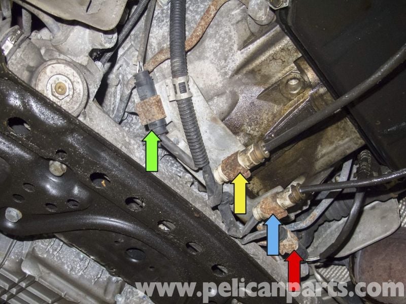
Step 3 – Identify the O2 sensor and connector locations
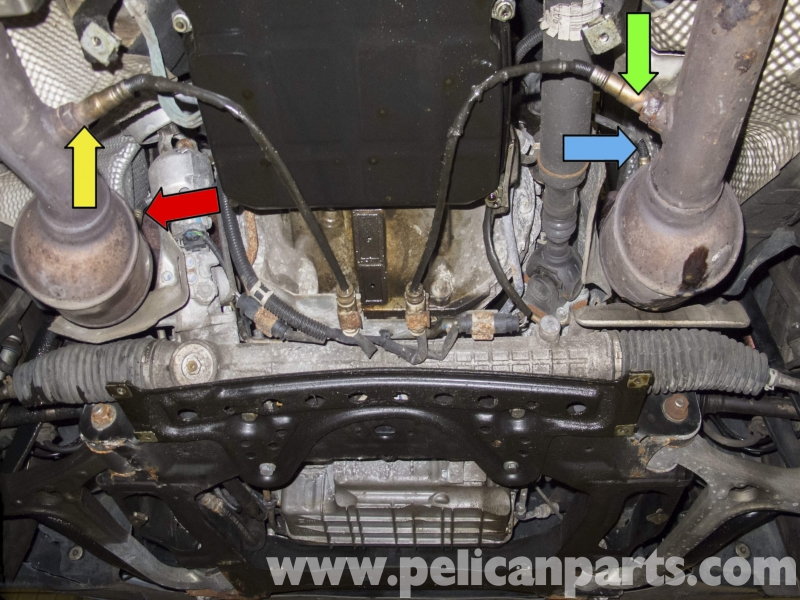
Sensors in Figure 12:
- Bank 1 Sensor 1, blue arrow
- Bank 2 Sensor 1, red arrow
- Bank 1 Sensor 2, green arrow
- Bank 2 Sensor 2, yellow arrow
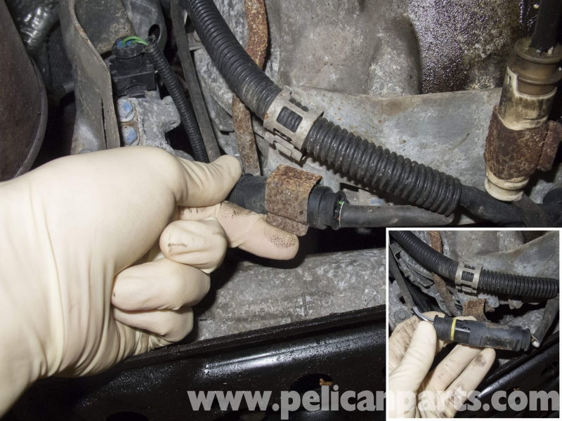
Sensor connectors in Figure 13:
- Bank 1 Sensor 1, red arrow
- Bank 2 Sensor 1, green arrow
- Bank 1 Sensor 2, blue arrow
- Bank 2 Sensor 2, yellow arrow
Pro Tip
If your vehicle is dirty, it's helpful to apply penetrating oil to the O2 sensors before loosening them. Let the oil soak for several minutes.
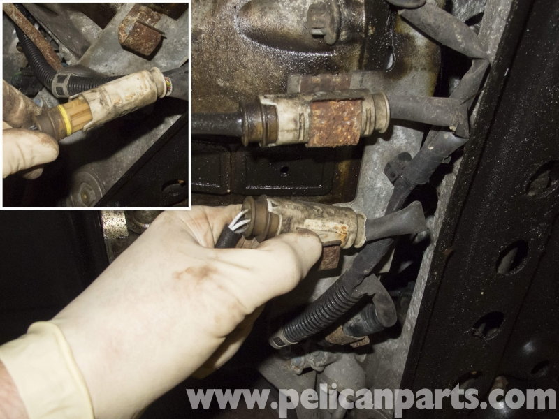
Step 4 – Disconnect the O2 sensor connector(s)
Begin by disconnecting the O2 sensor wiring connectors. Pull the metal tab up while pushing on the connector to release it from the metal mount. Then, disconnect the connector by pulling them apart. A flat head screwdriver may be needed to lift up on the connector tabs while pulling. Take note of the wiring harness path for re-installation.
Pro Tip
Marking the connectors or removing them one at a time makes it easier to remember which plug they connect to.
Step 5 – Remove the O2 sensors
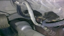
First, remove the uppermost O2 sensors. Follow the path of the wiring harness up to the sensor and remove any zip ties with diagonal cutters. Use your O2 sensor socket to break the O2 sensor free from the exhaust. Repeat the process for the remaining three O2 sensors.
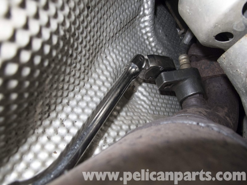
Figure 15. An O2 sensor socket is being used to loosen the upper O2 sensor. 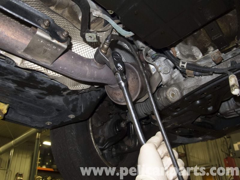
Figure 16. The lower O2 sensor is being removed.
Step 6 – Install the O2 sensor(s)
Apply anti-seize to the O2 sensor threads. Torque the sensors to 37 ft. lb. (50Nm.). Reconnect the connectors and install them into the metal mounts. Zip-tie any section of wiring that is hanging loosely out of the way of moving parts or high levels of heat.
Step 7 – Re-install the splash shields
Re-install the splash shields in the reverse order of removal. Position the rear splash shield first, then secure the fasteners by hand. Slide the front lower cover into place above the front bumper lip and tighten those fasteners as well. Lower the vehicle.
To verify the repair, clear any DTC's (Diagnostic Trouble Codes) that are present. Most service centers or parts store will do this for free.
Related Sites
- Lower Splash Shield Removal - Pelicanparts.com
- Jacking and Supporting the Vehicle - Pelicanparts.com
- O2 Sensor Replacement - Pelicanparts.com
- OBD2 Code List - OBD-codes.com