Mercedes-Benz C-Class: How to Replace Brake Pads and Rotors
This article will cover the process of brake pad and rotor replacement for your Mercedes-Benz C-Class. Diagnostic information has been included to help you determine if your brake rotors are worn past their minimum thickness level.
This article applies to the Mercedes-Benz C-Class Non-AMG (2007-2014). See Related Discussions below for the AMG version of this how-to for the c63.
The contact between the brake pads and rotors creates friction that slows the vehicle down. The larger the brake pad contact area, the more stopping power that is available to the driver. Friction also creates heat which can be damaging to pads and rotors. Rotors can warp causing a brake pedal pulsation, and brake pads will wear prematurely if the heat is not dissipated, requiring replacement.

Materials Needed
- Brake pad(s) P/N 005 420 12 20 (OEM equivalent)
- Brake rotor(s) P/N 2044210912 (OEM equivalent)
- Rubber mallet
- 17mm thin profile wrench
- 18mm, 13mm, and 8mm sockets
- Ratcheting wrench (preferably with a long handle)
- T27 Torx socket
- T45 Torx socket
- Brake caliper piston compression tool
- Floor jack and jack stands
- Caliper hanger
- Flat head screwdriver
- Micrometer or digital caliper (optional)
- Brake cleaner (optional)
- Disk brake pad grease
- Needle nose pliers
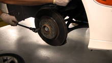
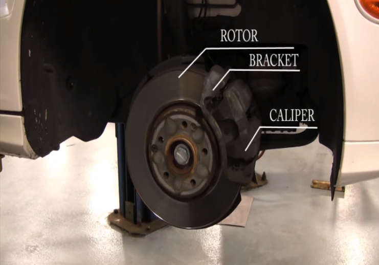
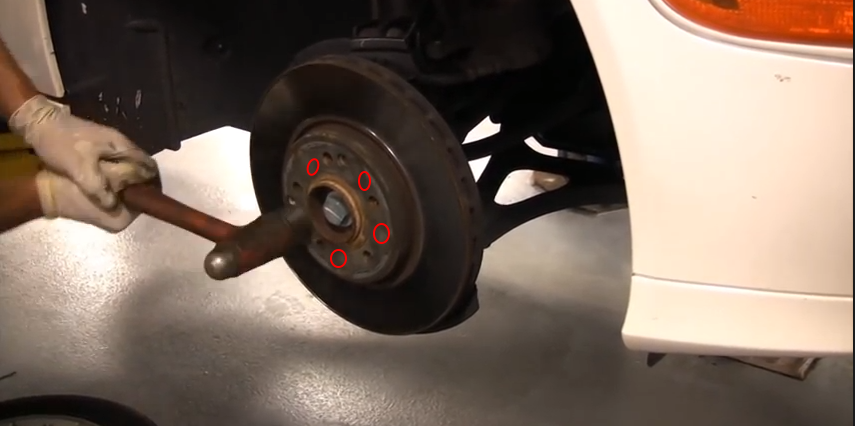
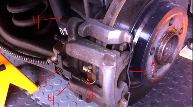
First, identify the brake rotor, caliper, and caliper bracket.
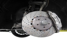
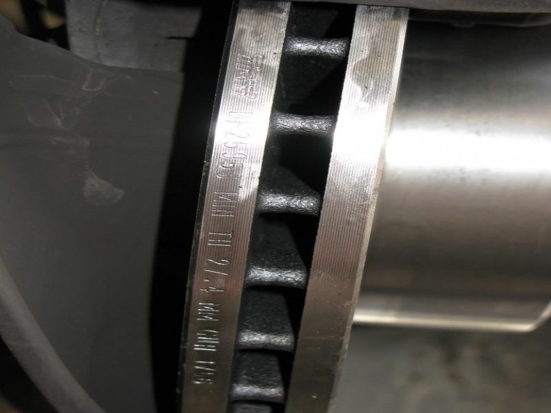
To determine if your brake rotor is in specification, locate the minimum thickness stamp on the rotor. It may be on the front, back, or side. The spec will most likely be listed in millimeters.
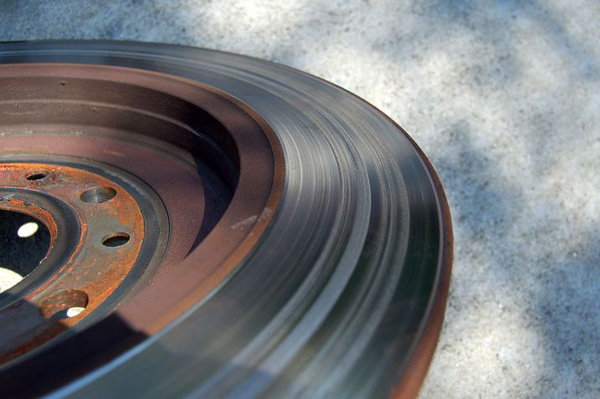
If your rotor resembles the one in Figure 3, then it's in need of replacement; there may also be another braking problem such as a binding brake caliper.
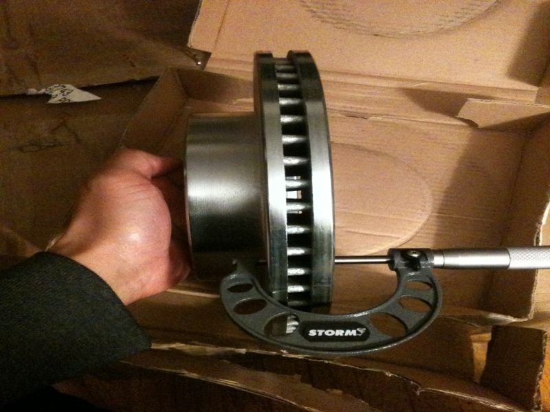
Using a digital caliper or a micrometer as in Figure 4, the rotor thickness can be measured.
To make this how-to more organized, the front brake pad and rotor replacement will be covered first.
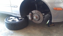
Step 1 – Raise and support the vehicle
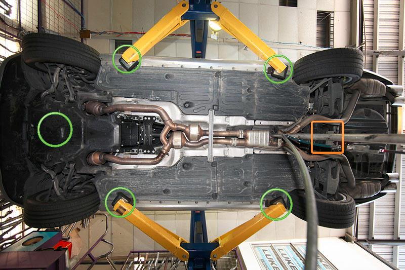
Lift your vehicle up and support it on jack stands. Your W204 has several jacking points that can be used, including the rear differential, the front subframe and the side jack stand mount pads. With the vehicle in the air, remove the wheels.
(Related Article: How to Jack Up Your C-Class - MBWorld.org)
Step 2 – Remove the front brake caliper(s)
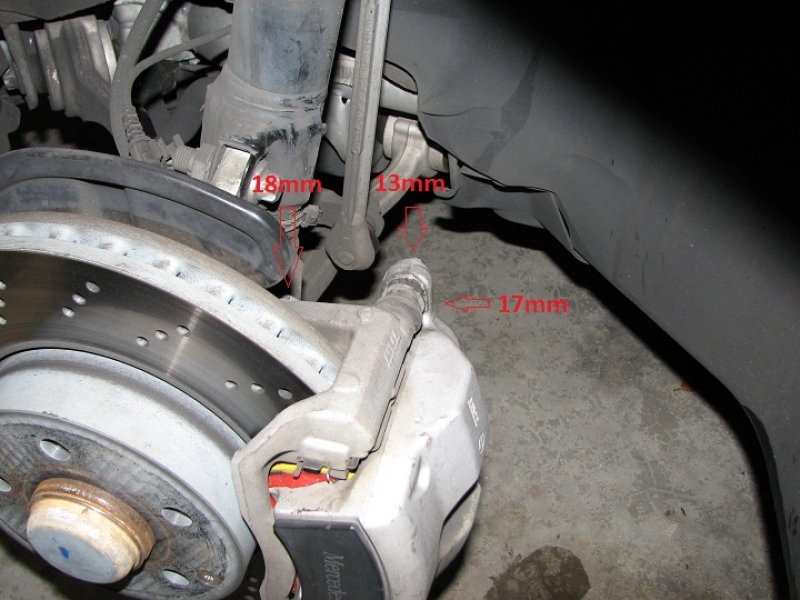
Once the wheel has been removed, turn the steering wheel to allow more clearance for the rotor. The front caliper is held on by two 13mm bolts that also have 17mm nuts. The 17mm nut needs to be held in place with the thin profile wrench while turning the bolt counter-clockwise.
The passenger side has a brake wear sensor that disconnects by pulling it apart at the connector.
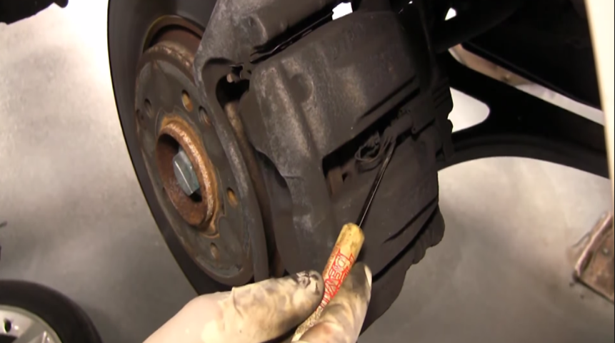
Figure 7. The brake wear sensor connector. 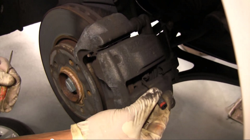
Figure 8. The brake wear sensor has been disconnected.
Pull up and away from the rotor, and the caliper will come right off. If it does not, then the caliper piston may need to be pushed in some. Grab the inner side of the caliper and pull it towards the rotor which creates space between the piston and rotor.
Use a caliper hanger to eliminate the chance of the rubber brake line becoming damaged.
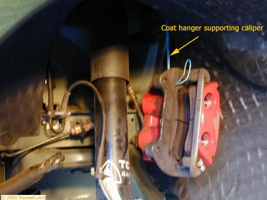
Pro Tip
Zip ties, coat hangers, and many other items can be used to secure the caliper. Zip-tie them to the strut or spring to get them out of the way. Make sure to leave slack in the brake lines while being hung.
Step 3 – Remove the front brake pads
Removing the front brake pads is easy. Simply slide them away from the rotor and out of the caliper bracket.
If your new brake pads did not come with the metal clips on the caliper bracket, you can reuse the old ones if they are not damaged. Be careful removing them as they will bend easily. Carefully pry them off the bracket with your screwdriver. This backing plate can be reused on the new pads, if they did not come with them. It is important to have this backing plate installed to limit pad movement and noise.
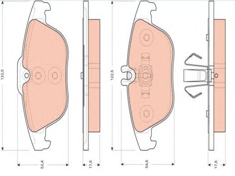
Figure 10. You can see the small metal clip that presses onto the brake pad. This holds the sensor in place. 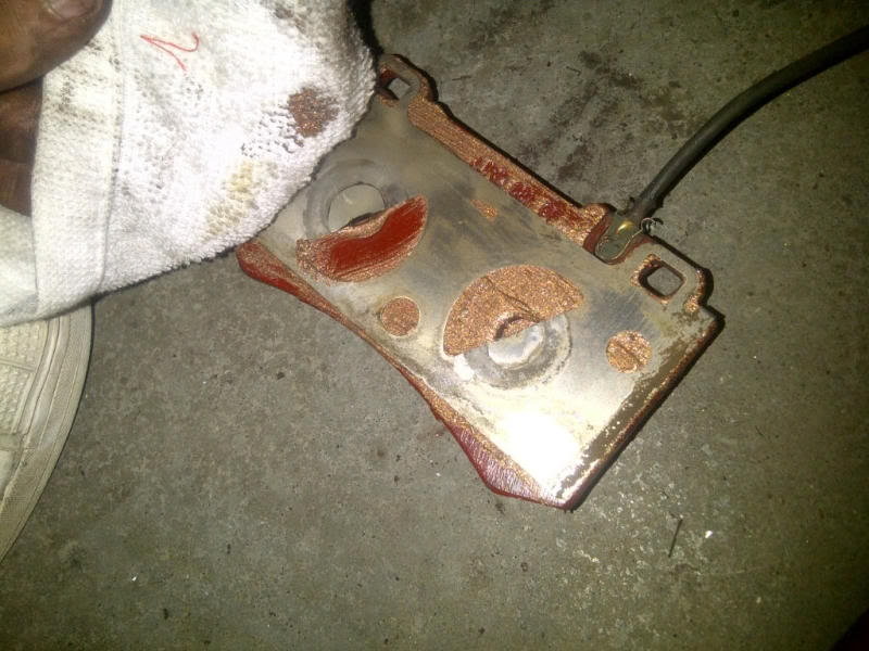
Figure 11. The metal clip is holding the sensor into the pad.
Step 4 – Compress the front caliper pistons
Using a suitable brake caliper compression tool (a C-clamp and an old brake pad works ok), squeeze the piston back into the caliper. Do not compress the piston all the way in. About a 1/4" protruding from the caliper is enough. Otherwise, the rubber piston boot will be damaged.
Note
Before compressing the brake caliper pistons, check the brake fluid level in the brake master cylinder. The fluid will rise as the piston is compressed. If it is near or above full, you will need to use a fluid transfer pump to prevent it from spilling over.
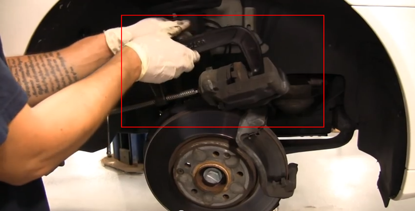
Figure 12. A C-clamp and old brake pad is being used to compress the caliper piston. 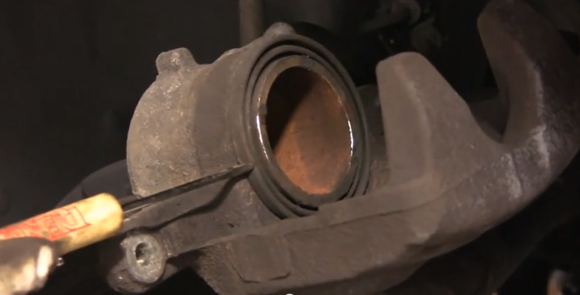
Figure 13. This caliper piston has been compressed the correct amount.
Step 5 – Remove the brake caliper bracket(s)
Removal of the brake caliper brackets only requires taking off two 18mm bolts.
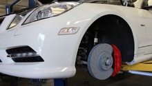
Step 6 – Remove the rotor(s)
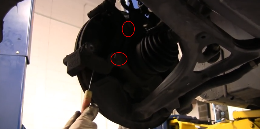
Remove the t27 Torx bolt (shaped like a star) from the rotor. The bolt centers and locates the rotor to the hub. The rotor should be free to be removed at this point.
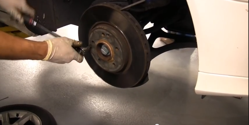
The rotor will now wiggle off the hub; pull towards you as you wiggle. If the rotor is stuck, use the mallet to break the rotor free. You will have to tap the middle section of the rotor.
Step 7 – Install new rotors and brake pads
Installation is the reverse of the removal.
- Clean the rotor and caliper by spraying it down with brake cleaner. This helps keep the brakes from becoming noisy. Be careful not to spray brake cleaner on rubber (brake line, caliper piston boot, dust covers, etc).
- Apply disk brake pad grease on the contact areas of the brake pad. This is where the caliper piston meets the back of the brake pad, and where the brake pads slides onto the metal clips that snap onto the caliper bracket.
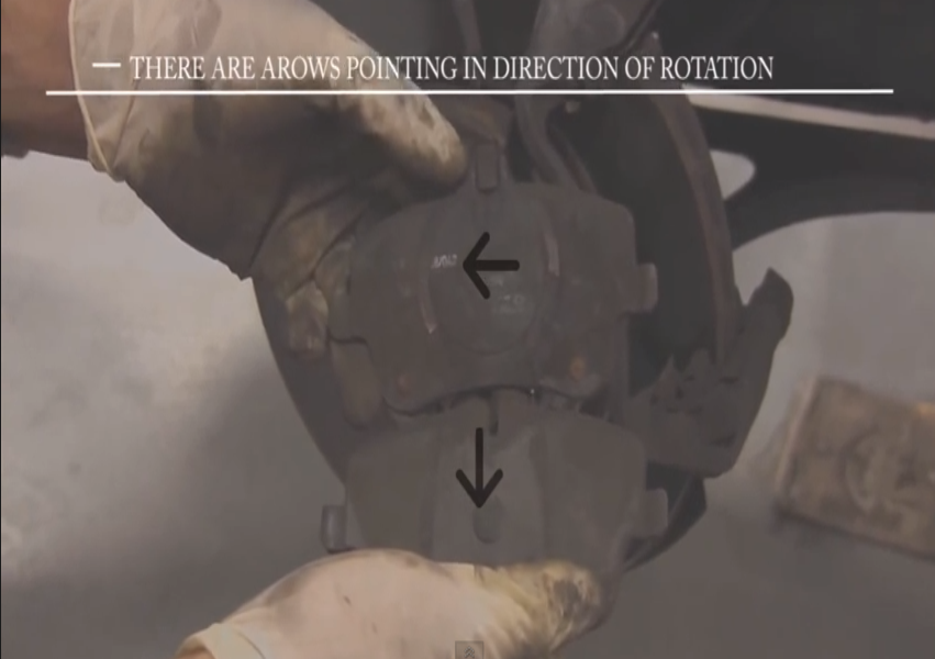
- Your brakes pads may be directional and marked with an arrow. Install the arrows in the direction of wheel rotation unless the directions say otherwise.
Featured Video: Front Brake Pad Removal
Step 8 – Remove/Install the rear calipers, pads, and rotors
The process for the rear is similar to the front, although there are some keys differences:
- There are metal clips that keep tension on the brake pad that must be removed from the caliper.
- There are two bolts (sliding pins) that require a t45 socket to be removed. There are rubber boots that cover these bolts. The boots simply pull off the head of the bolts.
- The brake wear sensor is held in place on the caliper by an 8mm bolt. The sensor itself may have a plastic fitting instead of a metal clip securing it to the brake pad.
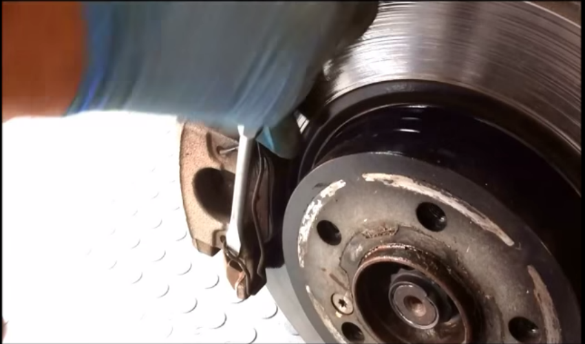
Figure 19. Using a flat head screwdriver to pry off the metal clip from the caliper. 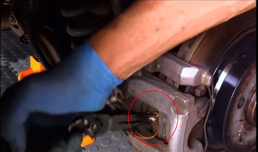
Figure 20. Removing the plastic break wear sensor. - The inner brake pads will have a three-prong clip that snaps into the caliper piston. If you have trouble snapping it into place, bend the prongs slightly.
- The two larger bolts (18mm) holding the caliper bracket to the hub may actually be Torx head bolts on some models.
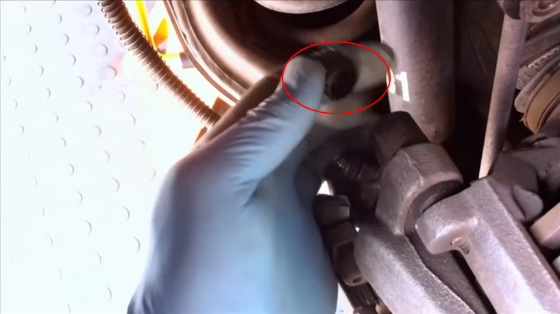
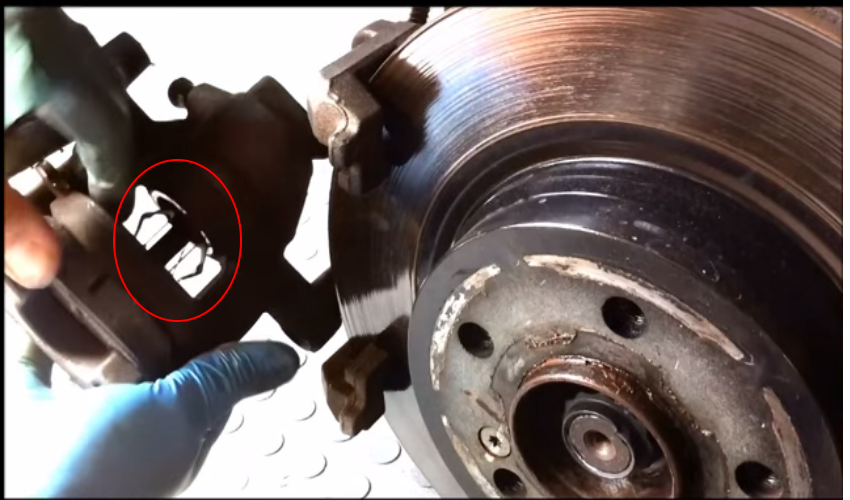
Figure 22 below represents the components of the rear brakes in a numbered format.
Once you have the wheels back on, remember to check the brake master cylinder again for the correct fluid level. Also be sure to press the brake pedal a couple of times; you will feel the brake pedal become firm, indicating that the brakes are working.
Featured Video: Rear Brake Pad Removal
Related Discussions
- DIY Front Brake Pad Change - MBWorld.org
- C-Class AMG: How to Replace Brake Pads/Calipers/Rotors - MBWorld.org